Laser Damage Threshold Testing

Laser Damage Threshold (LDT), also known as Laser Induced Damage Threshold (LIDT), is one of the most important specifications to consider when integrating an optical component such as a mirror into a laser system. Using a laser in an application offers a variety of benefits to a standard light source, including monochromaticity, directionality, and coherence. Laser beams often contain high energies and are capable of damaging sensitive optical components. When integrating a laser and optical components into a system, it is crucial to understand the effects of laser beams on optical surfaces and how laser damage threshold is quantified for optical components.
The type of damage induced to an optical component by a laser beam is dependent on the wavelength, pulse length, polarization, rep rate, and spatial characteristics among other factors. During exposure to a continuous wave (CW) laser, failure can occur due to laser energy absorption and thermal damage or melting of the substrate material or the optical coating. The damage caused by a short nanosecond laser pulses is typically due to dielectric breakdown of the material that results from exposure to the high electric fields in the laser beam. For pulse widths in between these two regimes or for high rep rate laser systems, laser induced damage may result from a combination of thermally induced damage and breakdown. For ultrashort pulses, about 10ps or less, nonlinear mechanisms such as multiphoton absorption and multiphoton ionization become important.
Testing Laser Damage Threshold
Laser-Induced Damage Threshold (LIDT) testing is a good method for quantifying the amount of electromagnetic radiation an optical component can withstand. There are a variety of different LDT tests. For example, Edmund Optics follows the ISO-11254 procedures and methods, which is the industry standard for determining the laser damage threshold of an optical component. Utilizing the ISO-11254 standard enables the fair comparison between optical components from different manufacturers.
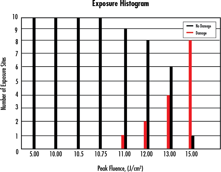
Edmund Optics' LDT testing is conducted by irradiating a number of test sites with a laser beam at different energy densities for pulsed lasers, or different power densities for CW lasers. The energy density or power density is incrementally increased at a minimum of ten sites at each increment. The process is repeated until damage is observed in of the irradiated sites. The LDT is the highest energy or power level at which no damage is observed in any of the irradiated sites. Inspection of the sites is done with a Nomarsky-type Differential Interference Contrast (DIC) microscope with 100X - 150X magnification. Visible damage is observed and the results are recorded using pass/fail criteria. Figure 1 is a typical damage probability plot of exposure sites as a function of laser pulse energy.

Figure 1: Exposure Histogram of Laser Damage Threshold Probability versus Exposure Site
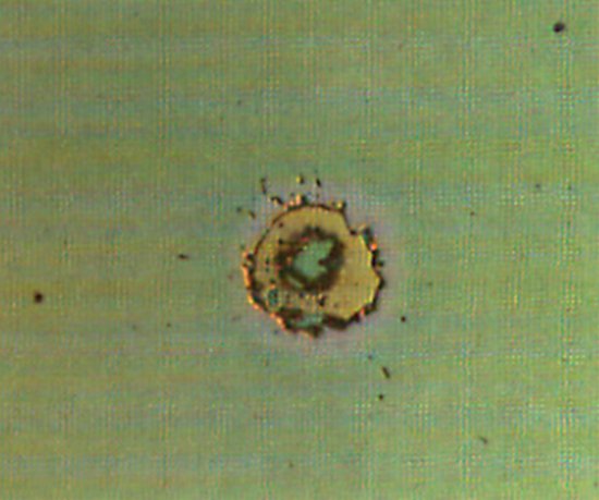
In addition to uncoated optical components, optical coatings are also subject to damage from the presence of absorption sites and plasma burn. Figure 2 is a real-world image of coating failure due to a coating defect. For additional information on the importance of LDT testing on coatings, view The Complexities of High-Power Optical Coatings.

Figure 2: Coating Failure from 73.3 J/cm2 Source due to Coating Defect
Defining Laser Damage Threshold
There are many variables that affect the Laser Damage Threshold (LDT) of an optical component. These variables can be separated into three categories: laser, substrate, and optical coating (Table 1).
Variables that Affect LDT/LIDT | ||
Laser | Substrate | Coating |
Output Power | Material | Deposited Material |
Pulse duration | Surface Quality | Deposition Process |
Pulse Repetition Rate | Cleanliness | Pre-Coating Preparation and Cleaning |
Beam Profile | Reactivity to the Environment | Lot-to-Lot Control |
Beam Diameter (1/e2) | Material Absorption | Coating Design and Optimization |
Wavelength | Material Homogeneity | Protective Layers |
LDT is typically quantified by power or energy densities for CW and pulsed lasers, respectively. Power density is the power per cross-sectional beam area of the laser beam (typically W/cm2). Similarly, energy density is the energy per cross-sectional beam area of a specific pulse duration (typically given in J/cm2). Lasers are available with a multitude of different wavelengths and pulse durations, therefore, it is useful to be able to scale LDT data to help determine if an optical component is suitable for use with a given laser. As a general rule of thumb, the following equation can be used to roughly estimate LDT from given data, LDT(λ1,τ1), LDT(λ2,τ2). This approximation only holds when scaling over relatively small wavelength or timescale ranges, and can not be used to extrapolate e.g. from ns to fs pulses, or from UV to IR.

In this equation τ1 is the laser pulse length and λ1 is the laser wavelength for the given LDT and τ2 is the laser pulse length and λ2 is the laser wavelength with unknown LDT. For example, the LDT for a mirror is 20 J/cm2 at 1064nm @ 20 ns. The LDT using the scaling rule above at 532nm and 10 ns pulse is 20 x (532/1064) x (10/20)½ or about 7 J/cm2. For longer pulses and high rep rate pulsed lasers it is also necessary to check the CW power density limit as well. The scaling equation is not applicable to ultra-short ps to fs pulsed lasers. When using “scaling” rules, safety factors of at least two times the calculated values should be applied to help ensure optical elements will not be damaged.
版权所有 © 2024 江阴韵翔光电技术有限公司 备案号:苏ICP备16003332号-1 技术支持:化工仪器网 管理登陆 GoogleSitemap